Exploration of methane hydrate and assessment of resources
Bottom Simulating Reflectors (BSR)
It has been known since the late 1960s to the early 1970s that “lines” appear in seismic survey records that cannot be explained as an ordinary accumulation of layers.
Since these records appear in parallel to each other at the seafloor, they were called “BSR (Bottom Simulating Reflectors).” Later studies have determined that BSR is a reflector that indicates the existence of methane hydrate. The following list shows the features of BSR.
- They are sonic reflectors that extend irrespective of the records of the neighboring orderly accumulated bedding plane
- They are in parallel with reflection records at the seafloor
- Their reflectional property is different from that of an ordinary layer reflector (reversed-phase in technical terminology)
The first step in exploring methane hydrate in an ocean is to find BSR by utilizing the seismic survey method.
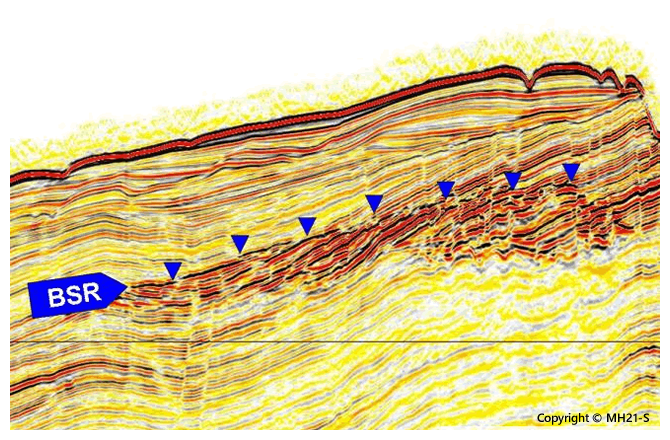
Fig.1 BSR that appeared in a seismic survey record
MH21 reviewed seismic survey data obtained in the areas surrounding Japan, and published in 2009.
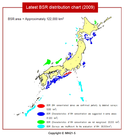
Fig.2 BSR distribution chart (2009)
METI* Exploratory Test Wells “Tokai-oki to Kumano-nada”
The following describes the outline of the FY2003 METI Exploratory Test Wells “Tokai-oki to Kumano-nada.” * Ministry of Economy, Trade and Industry
- The objective was to confirm the occurrence of methane hydrate in Tokai-oki to Kumano-nada (off the coast from Shizuoka Prefecture to Wakayama Prefecture) where its distribution has been predicted.
- The working period was from the end of January to mid-May 2004.
- Thirty two wells were drilled at 16 locations in three areas in Tokai-oki to Kumano-nada.
- The target water depth was approximately 700 to 2,000 m, and the drilling depth was 250 to 400 m below the seafloor.
- The riserless drilling vessel JOIDES Resolution was used for drilling operations.
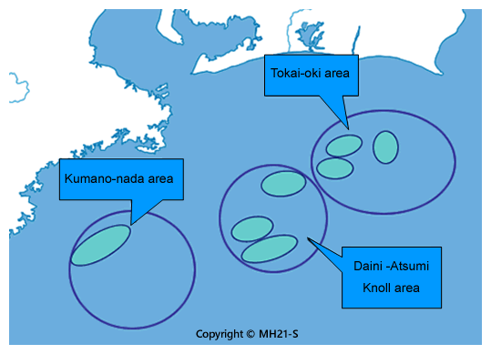
Fig.3 METI Exploratory Test Wells “Tokai-oki to Kumano-nada”
In the METI Exploratory Test Wells “Tokai-oki to Kumano-nada,” surveys were executed in line with the following five items.
- LWD: Logging While Drilling
- Wireline logging
- Coring(Geological sampling)
Methane hydrate layers and their upper and lower layers were sampled using the existing device (corer) and the PTCS (Pressure-Temperature Core Sampler) uniquely developed in Japan. - Demonstration experiment
MH21 conducted demonstration experiments on basic technologies, including mud technology, cementing technology and horizontal well drilling technology, along with the measurement of various parameters in wells that are required for future production tests of methane hydrate. - Installation of geothermometer
Methane hydrate stabilizes in a low temperature and high pressure environment. In particular, temperature is the key factor. The temperature distribution inside the methane hydrate-bearing layers is to date not clearly known. Therefore, MH21 has developed a unique optical-fiber distributed temperature sensor, and installed it in the wells after the wireline logging was finished.
Discovery of high saturation methane hydrate layers
The wireline logging discovered many layers that exhibit extremely high specific resistivity. The thickness of some layers reached as deep as 105 m. MH21 has conducted coring and sampled the layers with high specific resistivity.
Subsequent analyses have determined that these are methane hydrate layers containing particles of methane hydrate between the sand particles of the sandy sediments. Since the space between sand particles is called the pore, this type of methane hydrate is called “pore filling type methane hydrate.”
In addition, since further analyses detected that methane hydrate layers are mainly contained in the sandy sediments, they are now called “pore filling type methane hydrate layers in sandy sediments.”
The ratio of methane hydrate volume to the volume of pores is called methane hydrate saturation. Detailed analyses found that methane hydrate saturation reaches a maximum of approximately 80%. These layers are evaluated as “high-saturation methane hydrate layers.”
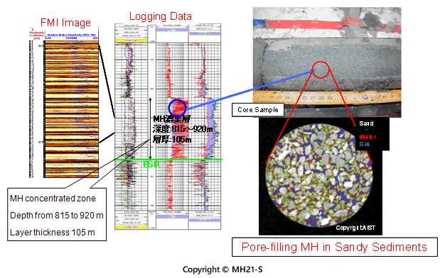
Fig.4 Pore filling type methane hydrate
Establishment of a methane hydrate concentrated zone exploration method
After the METI Exploratory Test Wells “Tokai-oki to Kumano-nada” were finished, MH21 attempted to establish a method to display in three dimensions the spread of the pore filling type methane hydrate layers in sandy sediments, based on a re-examination and re-analysis of the seismic survey data, which was obtained before the METI Exploratory Test Wells were conducted.
Researchers and engineers in the areas of geophysics, geology, sedimentology and geochemistry were assembled to take on this large task and finally succeeded in establishing the method.
MH21 decided to call the thick and wide distribution of the pore filling type methane hydrate layers in sandy sediments the “methane hydrate concentrated zone.” The methane hydrate concentrated zone is considered to be an ore deposit that can be developed using currently available technologies.
It was the first time in the world for such methane hydrate layers that have potential for large-scale development as a methane hydrate concentrated zone to be found.
It was determined from studies performed to date that the following four indices are critical in terms of estimating the distribution of methane hydrate concentrated zones from seismic survey data.
- Existence of BSRs
- Distribution of turbidite sand and mud alteration layers
- High amplitude reflector
- High velocity anomaly
It is considered that the methane hydrate concentrated zone is a layer that meets the above four indices. Japan is the first country to exhibit the four indices systematically.
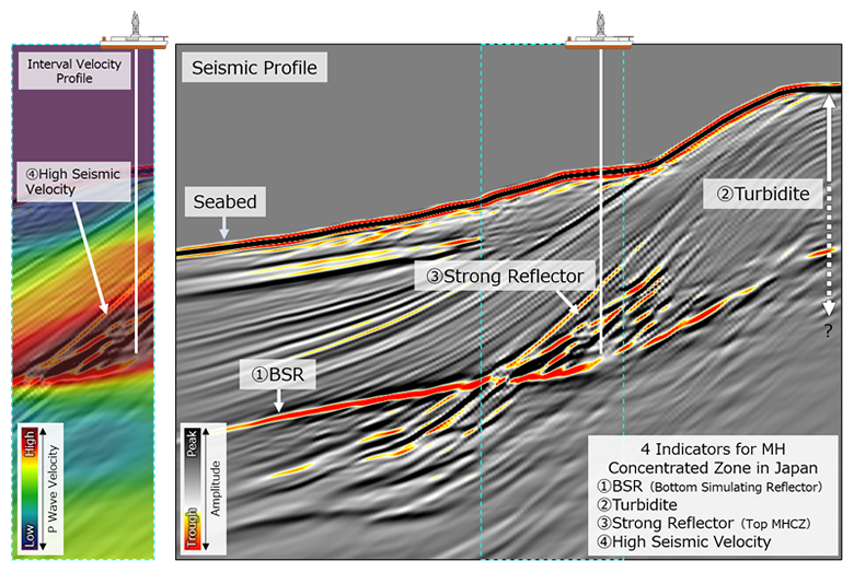
Fig.5 4 Indicators for MH Concentrated Zone in Japan
For details of the methane hydrate concentrated zone extraction method, refer to the following research papers.
Saeki, T. et. al, (2008): Extraction of Methane hydrate concentrated zone for resource Assessment in the Eastern Nankai Trough, Proceedings of the 2008 Offshore Technology Conference, OTC19311.
Resources assessment in the eastern Nankai Trough
A method for estimating the distribution of methane hydrate concentrated zones, which can potentially be developed, has been established. Thanks to the established method, MH21 is now able to determine the volume of the given methane hydrate concentrated zone.
The following equation is used when determining methane hydrate resources (the volume of methane gas in methane hydrate) in a methane hydrate concentrated zone. This method has been developed by modifying the “volumetric method” for obtaining the volume of oil and natural gas resources to be better suited for methane hydrate.
- Original methane gas in place = Total rock volume x Net/gross ratio x Porosity x Methane hydrate saturation x Volume ratio x Cage occupancy
This evaluation is based on a probabilistic approach similar to the evaluation used for oil and natural gas resources. “Pmean” in the following table denotes the most probable original methane gas in place.
MH21 is also determining the volume of the original methane gas in place in methane hydrate layers outside the methane hydrate concentrated zones using its own unique method.
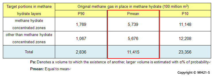
Table 1 Original gas in place in methane hydrate layers in a place other than methane hydrate concentrated zones of the eastern Nankai Trough
For details of the evaluation of original methane gas in place in the eastern Nankai Trough, refer to the following literature.
Fujii, T. et. al, (2008): Resource Assessment of Methane Hydrate in the Eastern Nankai Trough, Japan, Proceedings of 2008 Offshore Technology Conference, OTC19310.
The volume of methane in methane hydrate concentrated zones is 573.9 billion m3. This volume roughly corresponds to the volume of natural gas consumed over a period of approximately seven years in Japan. This volume may sound small, however, the concentrated zones are ranked the largest among natural gas fields. Considering the small amount of oil and natural gas resources in Japan, it is surprising that such a large volume of methane exists in a limited area of the eastern Nankai Trough.
The content covered up to this point can be summarized as follows:
- Although BSR indicates the existence of methane hydrate, it does not tell how methane hydrate is stored on BSR.
- Studies conducted by MH21 have discovered methane hydrate ore deposits with potential for development, which are called “methane hydrate concentrated zones.”
- MH21 has established a method for identifying the three-dimensional distribution of methane hydrate concentrated zones through a seismic survey.
- Using this method, MH21 has found more than 10 methane hydrate concentrated zones in the eastern Nankai Trough.
- MH21 has calculated the original methane gas in place within a methane hydrate concentrated zone in the eastern Nankai Trough using the probabilistic volumetric method that is normally used to assess oil and natural gas resources. The volume calculated corresponds to that of the largest gas fields.
- The original gas in place multiplied by the recovery factor is recoverable reserves. One of tasks of MH21-S in the future is to find a production method with a higher recovery factor.
