A long-term methane hydrate production test on the Alaska North Slope
-
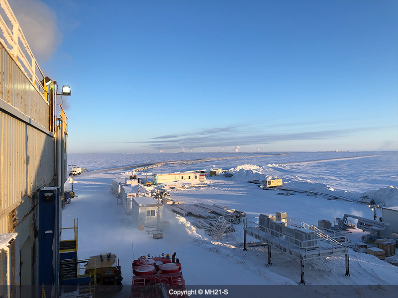
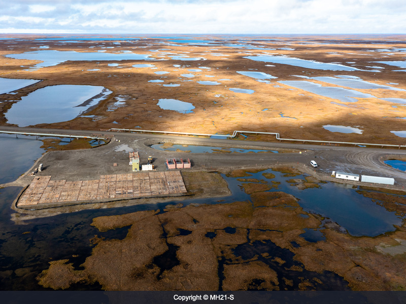 1)Scenery of 7-11-12 pad(late-Aug)
-
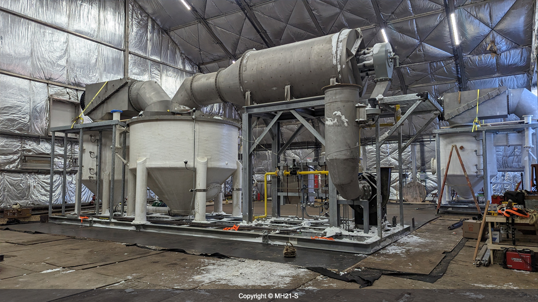
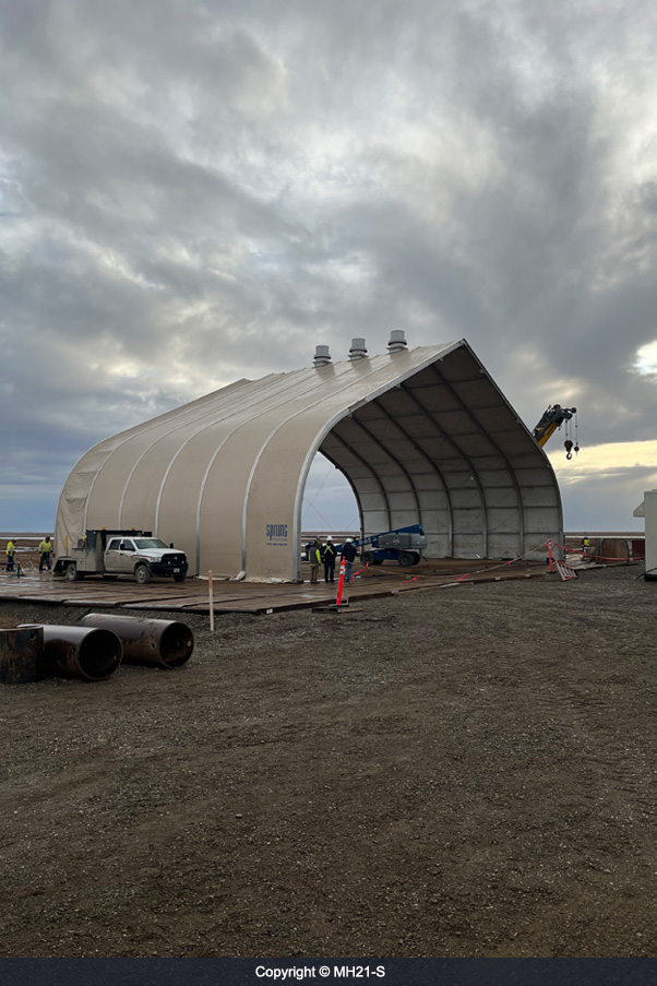 2)Sprung structure under construction
-
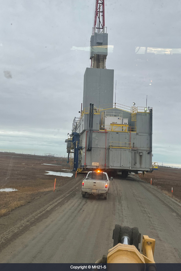 3)The rig under mobilization (mid-Sep)
-
 4)Preparation for drilling (late-Sep)
-
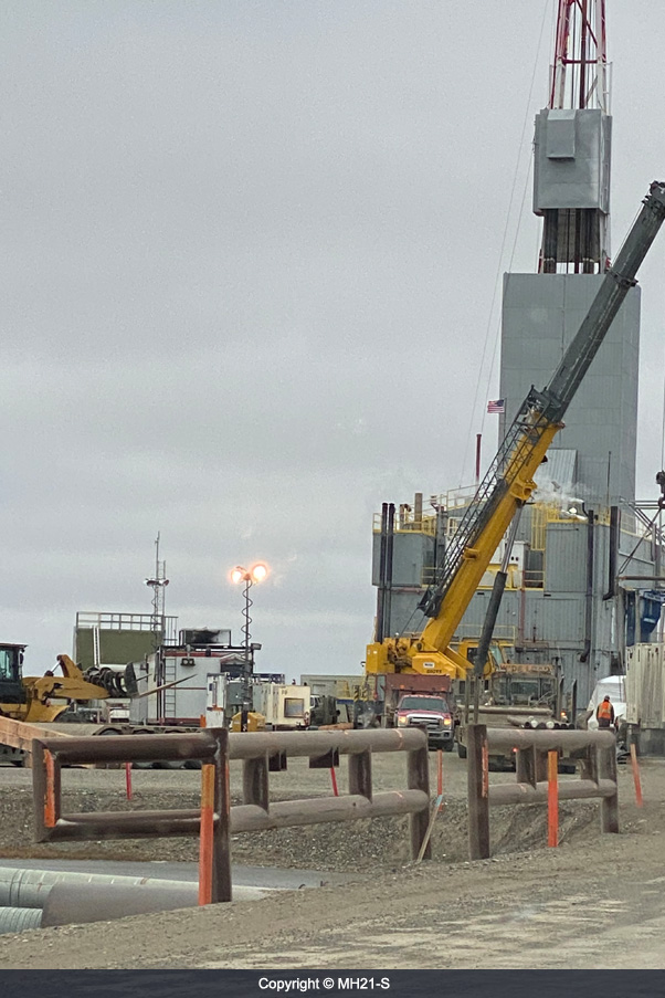
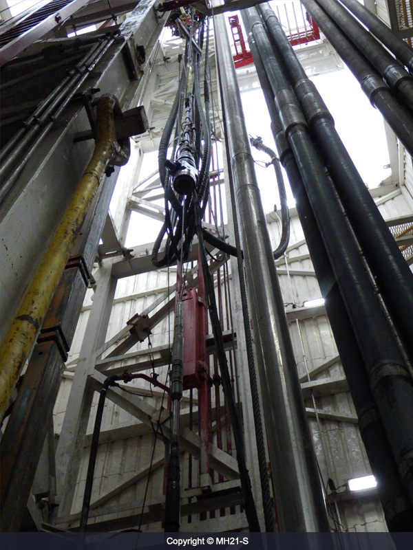
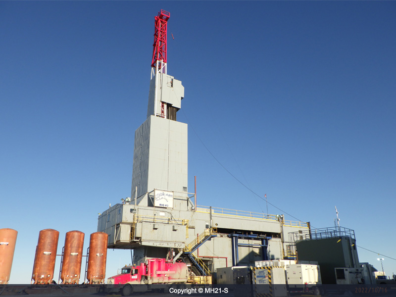 5)Drilling rig
-
 6) Drilling rig with huge tires
-
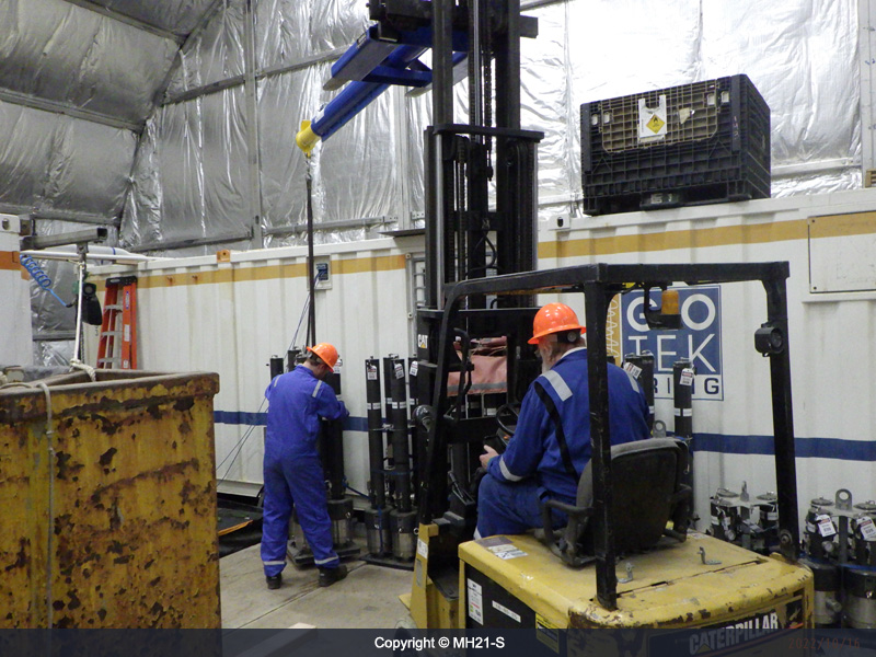 7)Preparation of pressure coring equipment
-
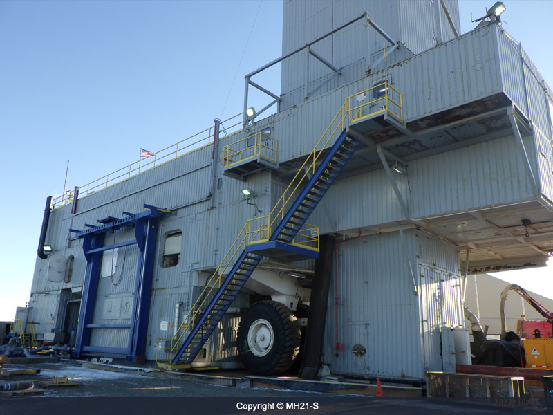
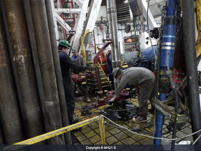
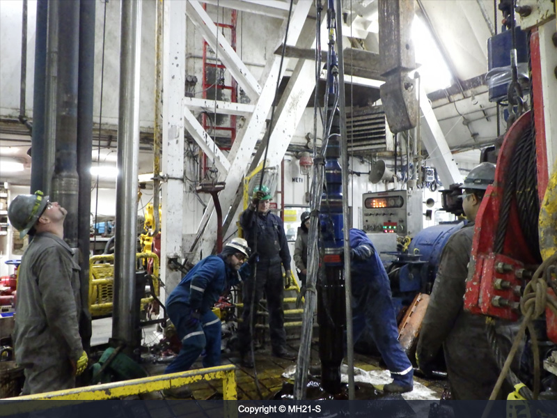
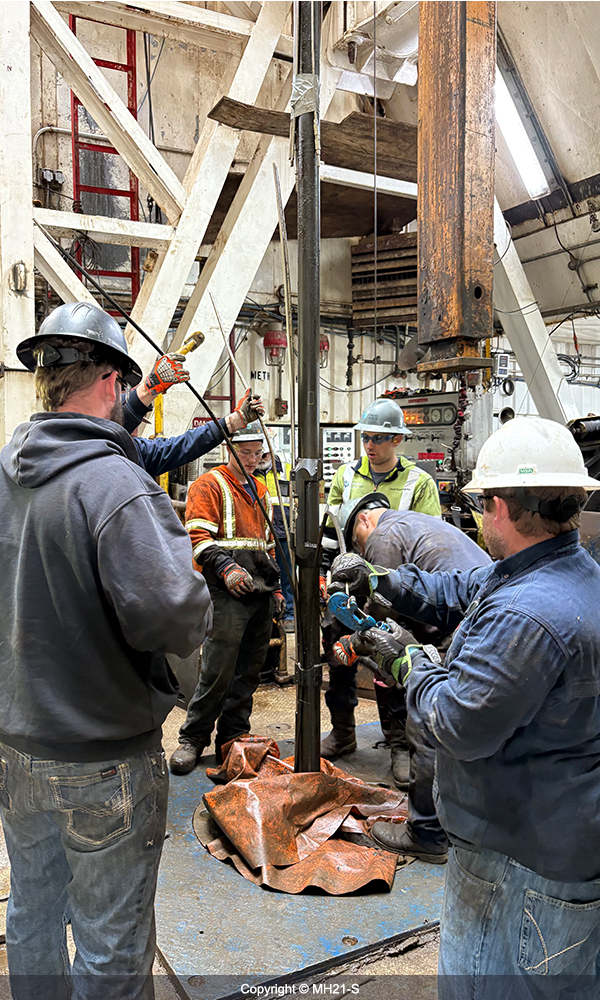
 8)Rig floor
-
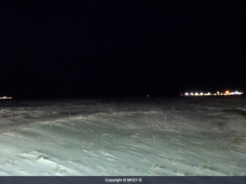
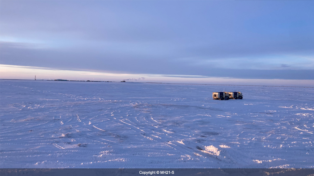
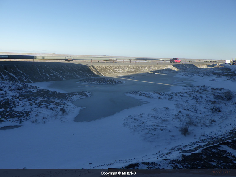 9)Scenery (mid-Oct)
-
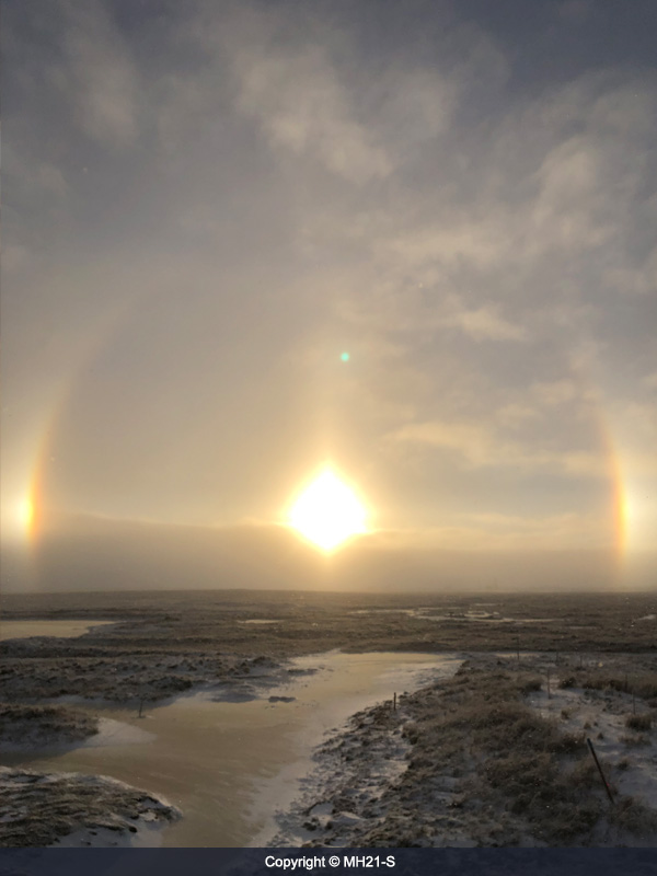 10)Sundog (Oct. 25)
-
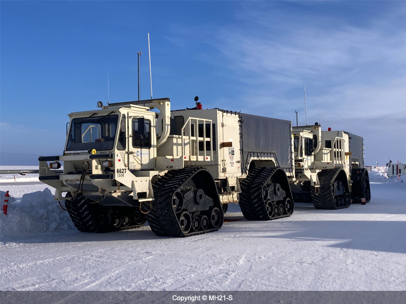
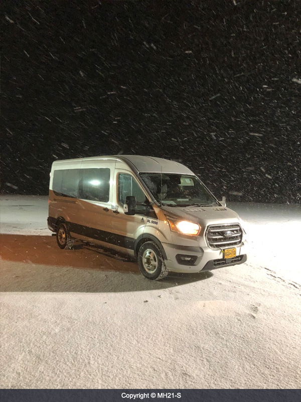 11)Shuttle Bus between the camp and the drill site in the snow(late - Oct)
-
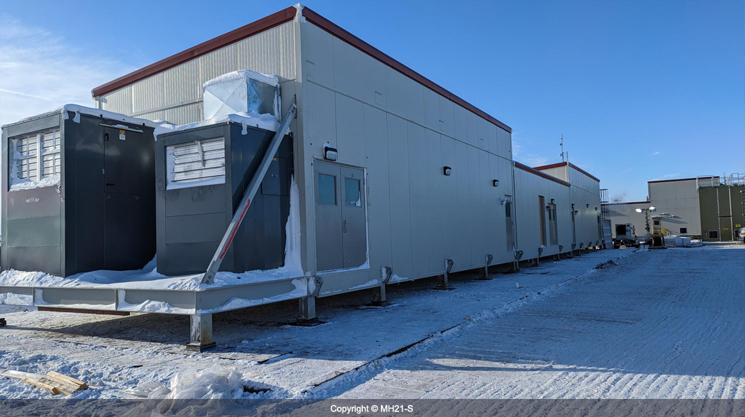
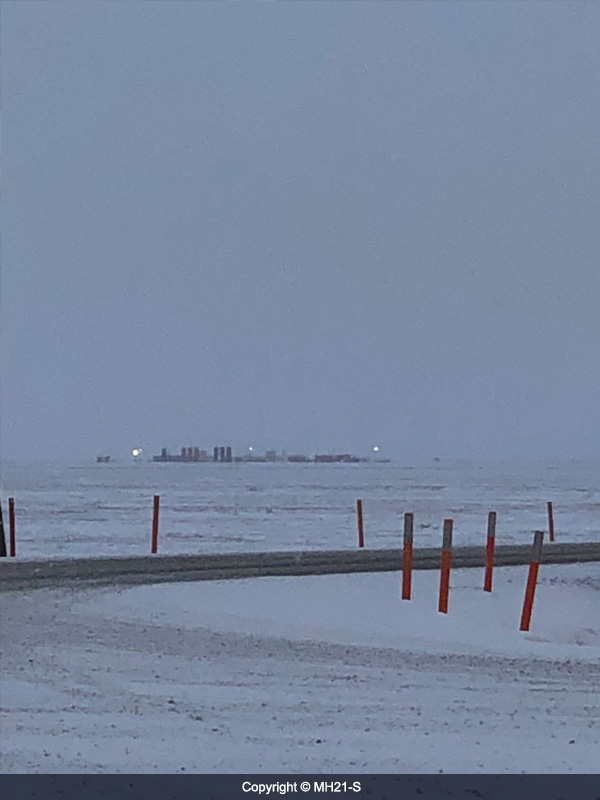 12)The camp view from 7-11-12 pad
-
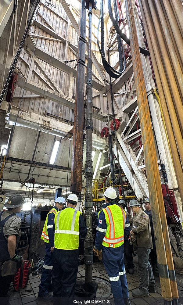
 13)Assembling LWD tools
-
 14)Scenery at 9 am (early Nov)
-
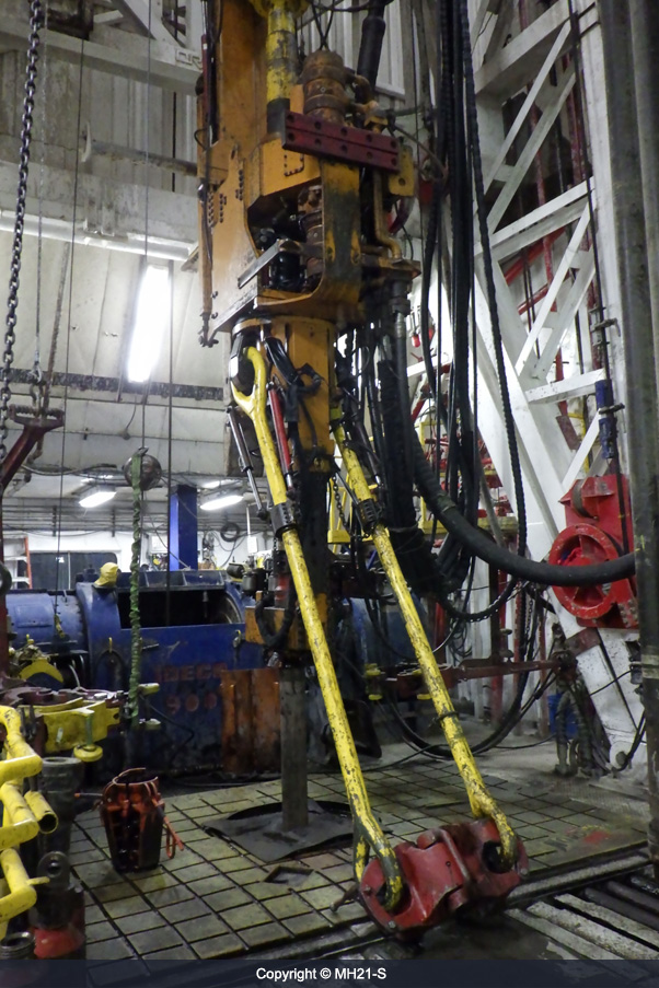
 15)Pressure Coring tools
-
 16)Pressure Coring
-
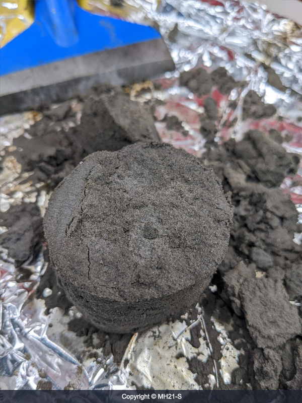 17)Methane hydrate-bearing sediment
-
 18)Quantitative degassing from pressure chamber
-
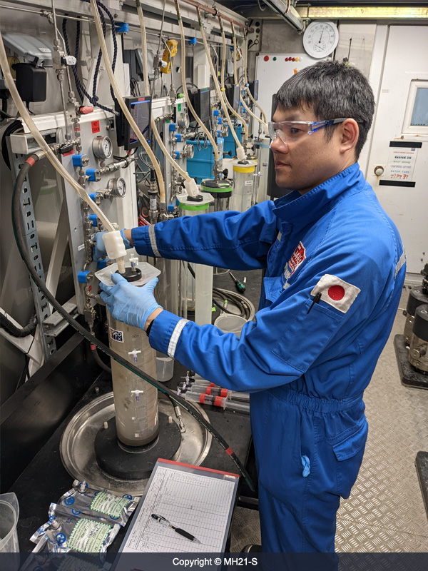
 19)Transfer for inner barrel containing pressure core to Pressure Core Analysis and Transfer System (PCATS)
-
 20)Core transfer to the Sprung Structure from the rig
-
 21)Core operation international joint team with MH21-S,USGS and Geotek
-
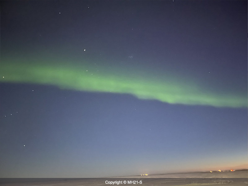
 22)Aurora
-
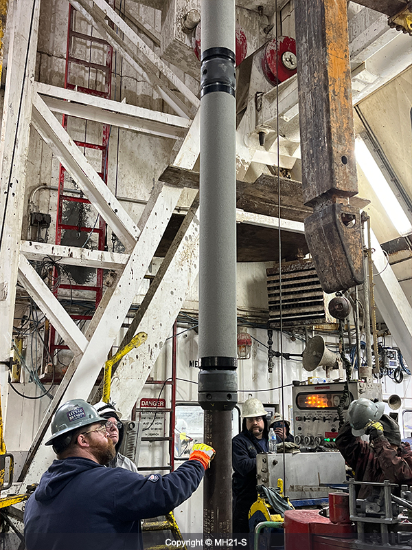
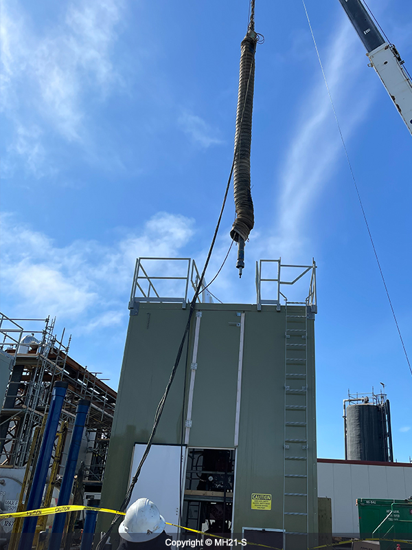
 23)Connecting Vacuum Insulated Casing (VIC)
-
 24)Sensor Cable Installation
-
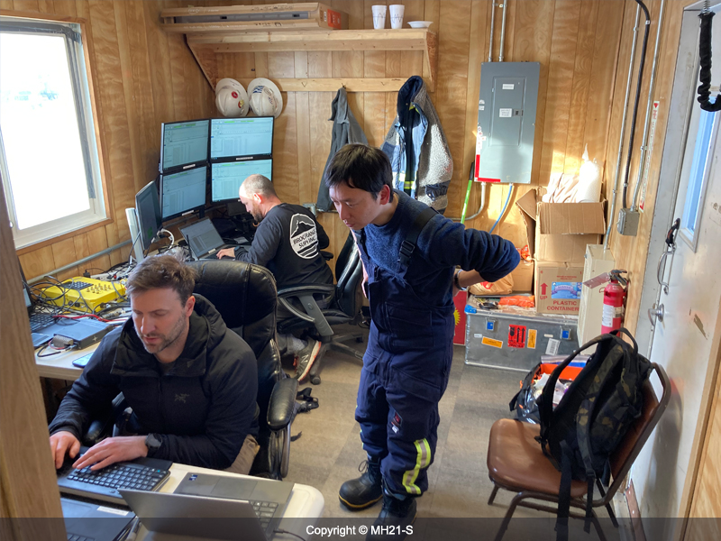
 25)Meeting in the Sprung Structure
-
 26)Installing Module 5(Desander module)
-
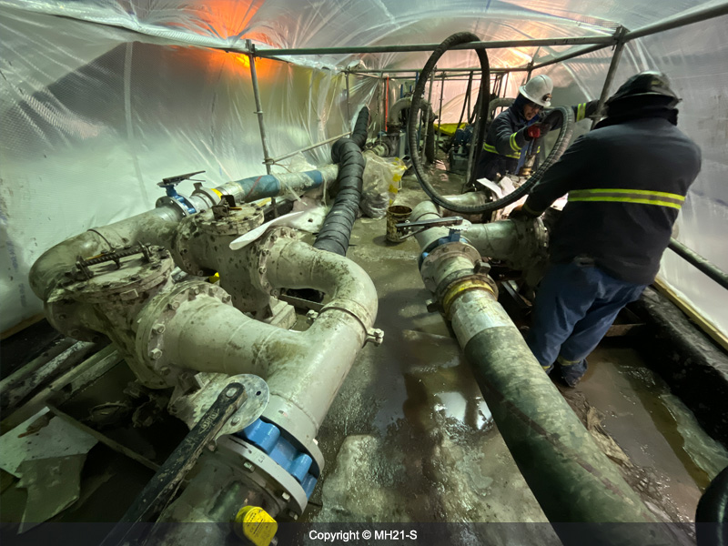
 27)Piping construction
-
 28)Ice pad construction
-
 29)Mud chiller filter
-
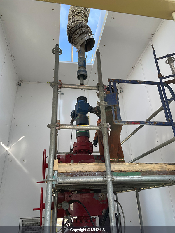
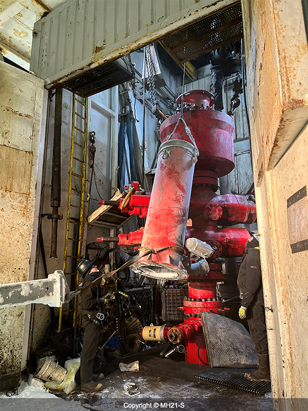 30)Nipple up BOP
-
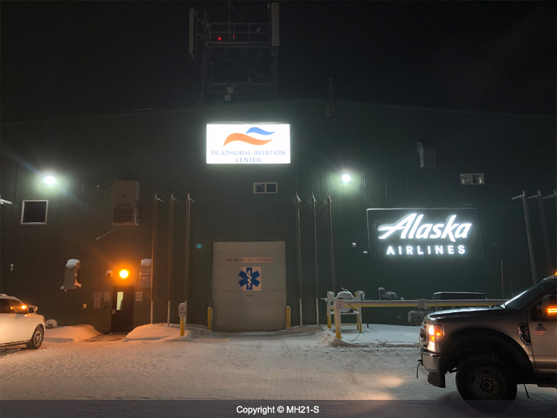 31)Deadhorse Airport
-
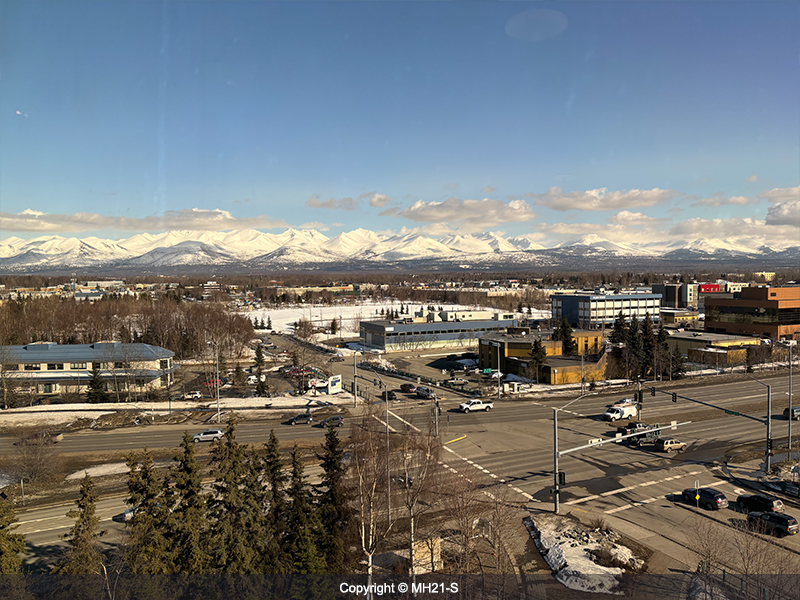
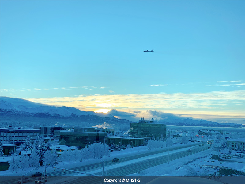 32)Scenery of Anchorage
-
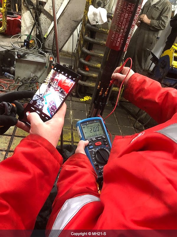 33)Electrical check of the power cable for the downhole electric heater
-
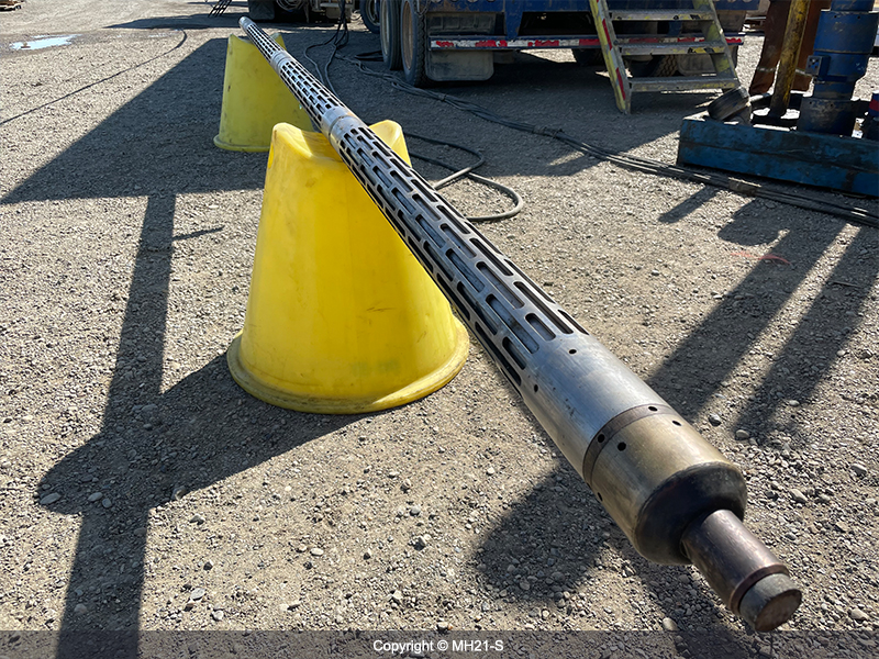
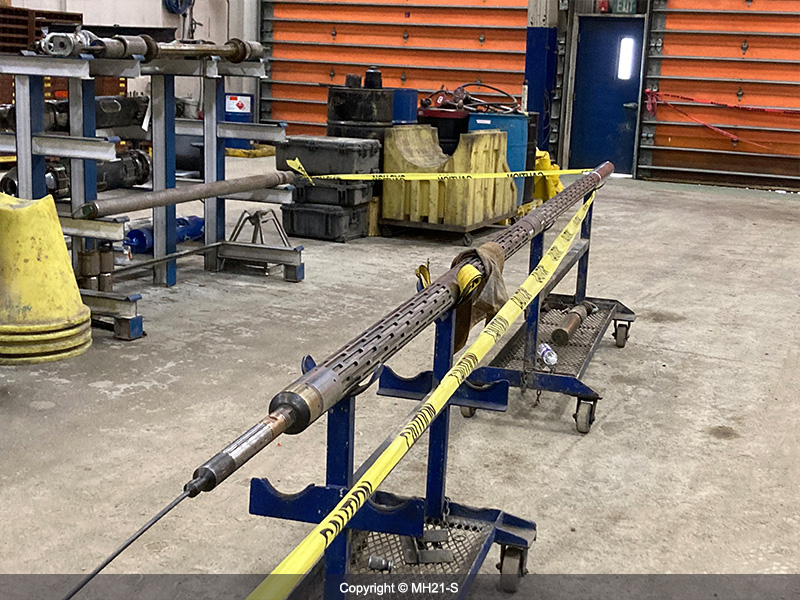
 34)Sand control device
-
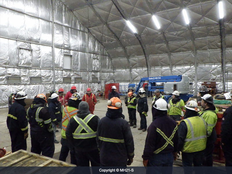
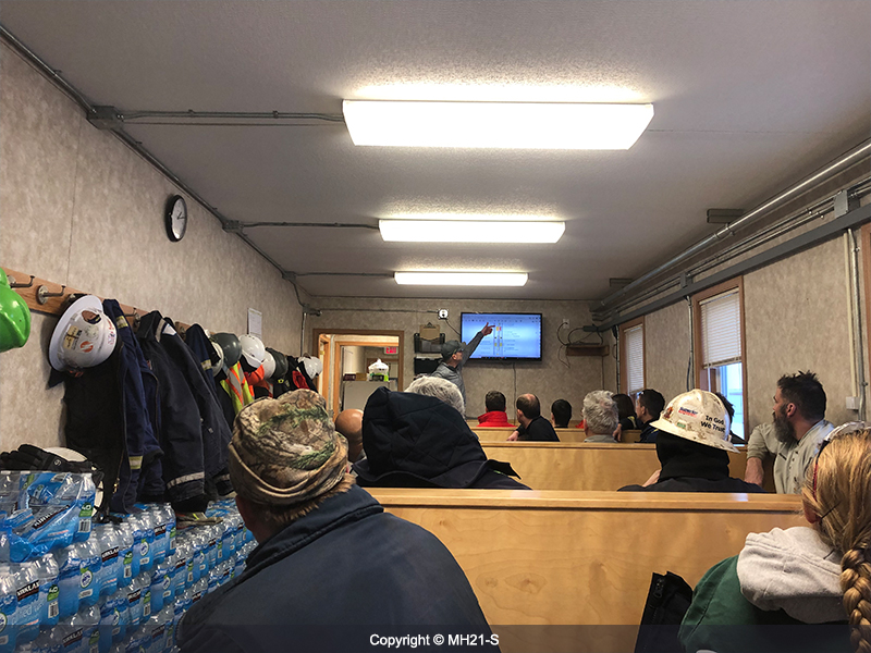 35)Pre-job safety meeting
-
 36)MH21-S members
-
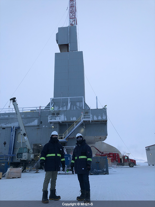
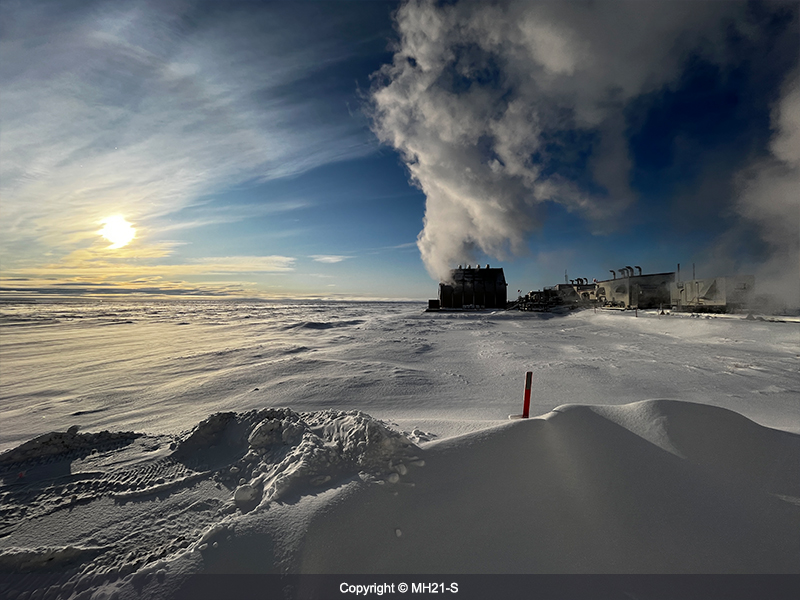
 37)Well-site at -34 degrees Celsius
-
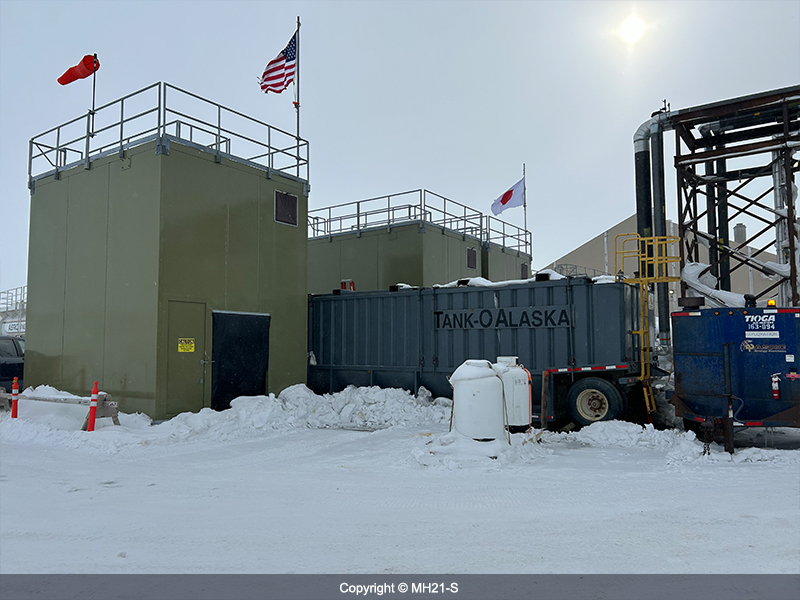
 38)Evaporator
-
 39)Installed generator and switchgear Module
-
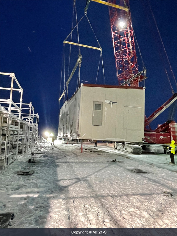
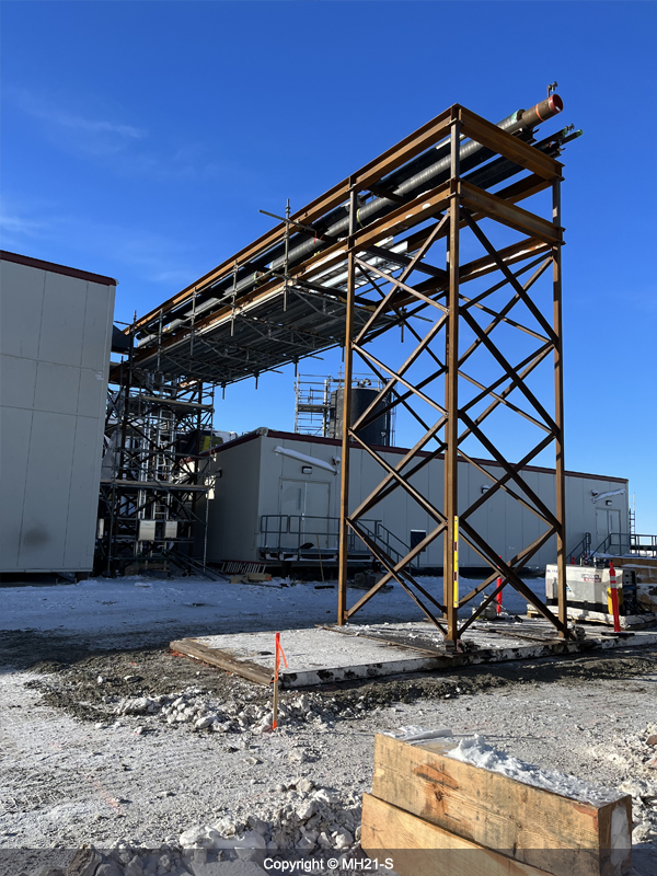 40)Pipe bridge under construction
-
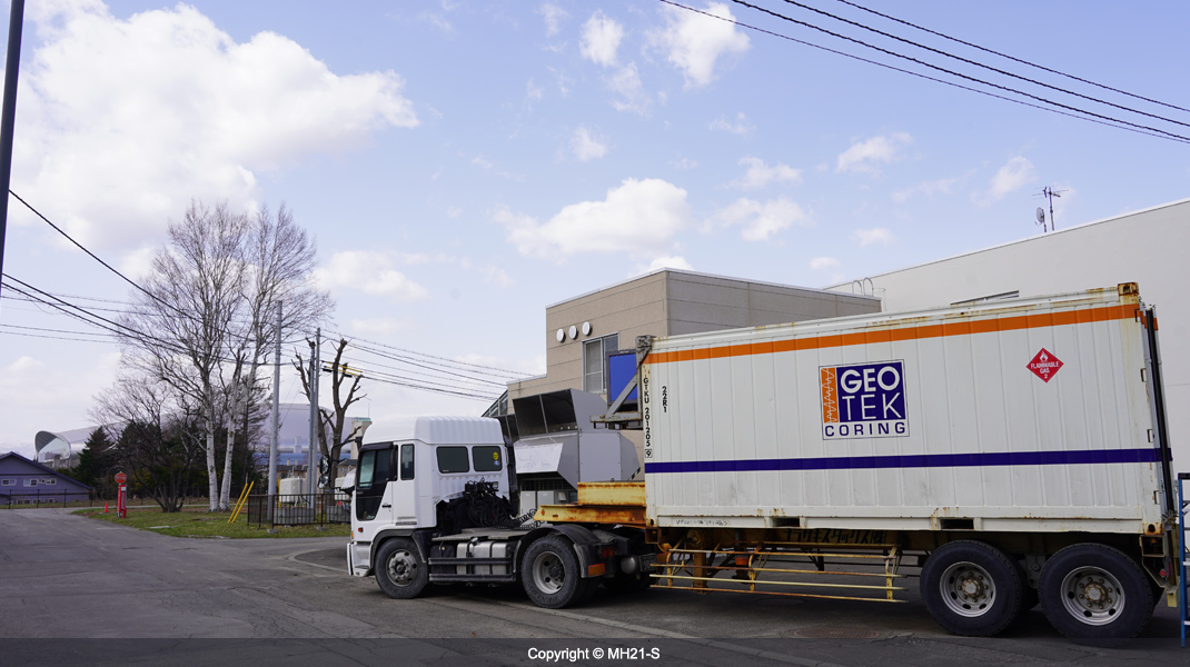 41)Pressure core arrival at the Hokkaido Center of AIST
-
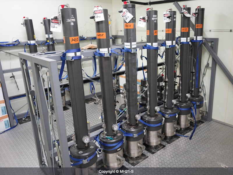 42)Storage chambers for pressure cores
-
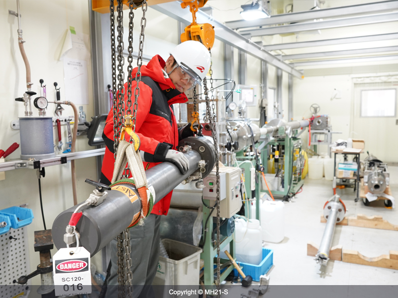 43)Core to be cut in the manipulator under pressure
-
 44)End surface of pressure core under 10 MPa of water pressure
-
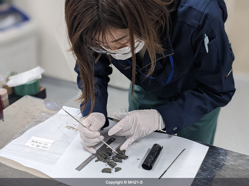 45)Sub-sampling after depressurization for further analyses (grain size, density, etc.)
-
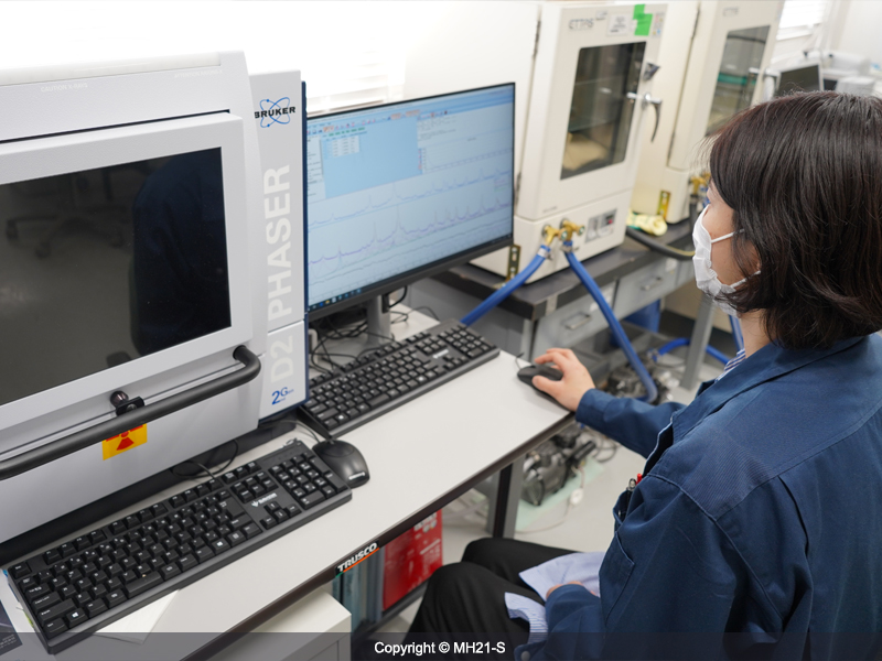 46)X-ray diffraction analysis for evaluating the mineral composition of sediments
-
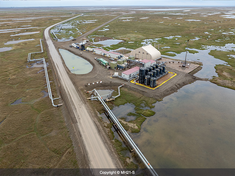
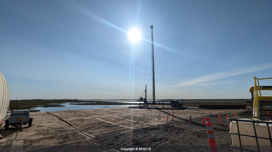
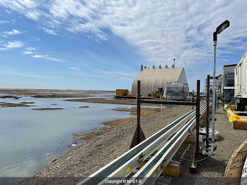 47)7-11-12 Gas hydrate test site (early-June 2023)
-
 48)Downhole seismic source
-
 49)Running into the hole with downhole seismic source(1)
-
 50)Running into the hole with downhole seismic source(2)
-
 51)Reviewing data acquisition procedures
-
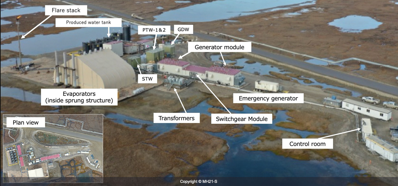
 52)Wellhouse, From left: STW, PTW-1、PTW-2、GDW (June 2023)
-
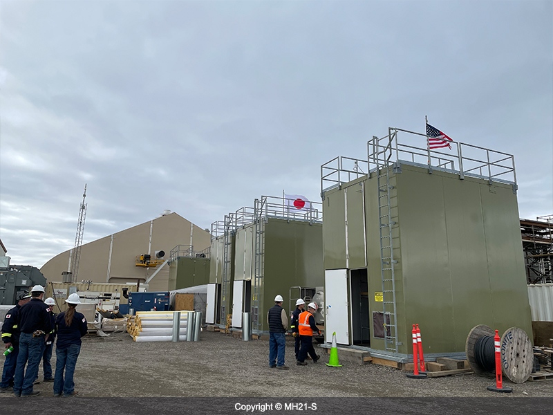
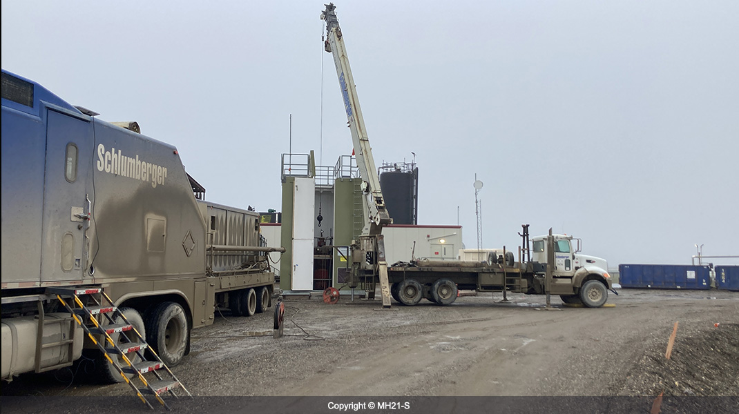
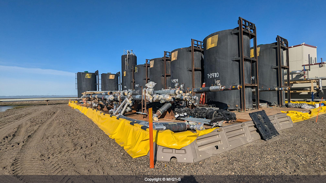
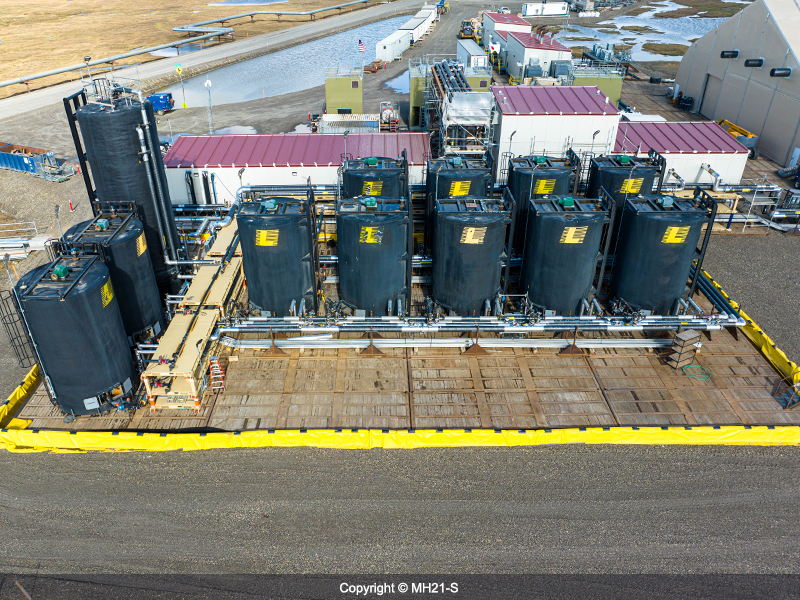 53)Tank yard
-
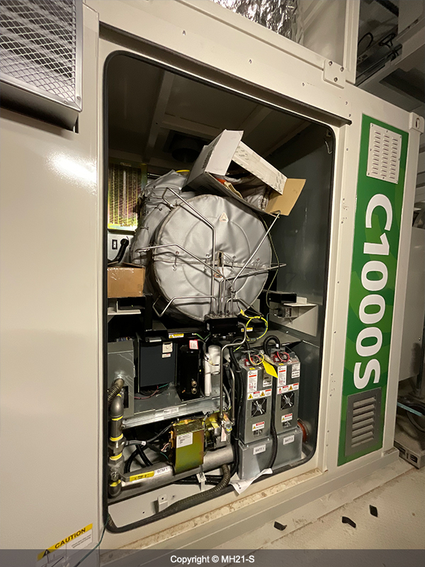 54)Microturbine generator
-
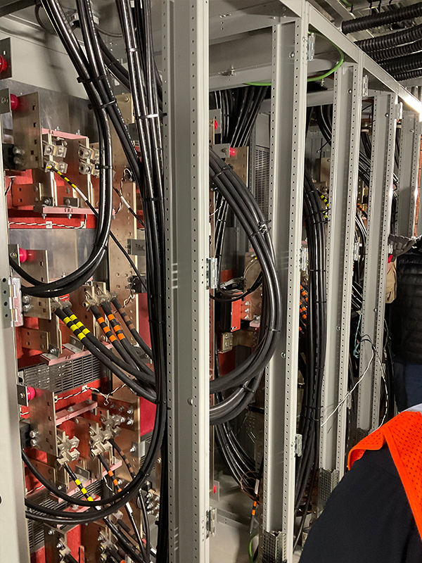 55)Switch gear
-
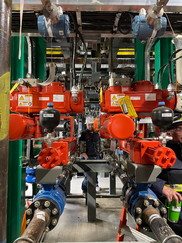 56)Desander unit
-
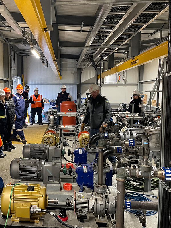 57)Pump module
-
 58)7-11-12 Gas hydrate test site (Aug 2023)
-
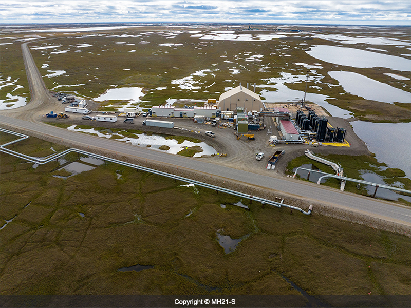
 59)Methane hydrate long-term production test site (Oct 2023)
-
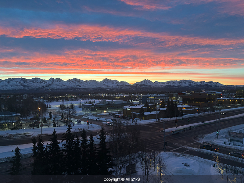 60)Morning glow view taken from the operator's office in Anchorage(Feb 2024)
-
 61)Research & Development Committee Meeting(RDC) held in Anchorage (April 2024)
-
 62)Spring in Anchorage (April 2024)
-
 63)Methane hydrate long-term production test site (April 2024)
-
 64)Long-term production test site (Sep 2023)
-
 65)Long-term production test site (July 2024)
-
 66)Downhole seismic sources(July 2024)
-
 67)Running into the hole with downhole seismic sources (1) (July 2024)
-
 68)Installation of the
wireline BOP(July 2024) -
 69)Running into the hole with downhole seismic sources (2) (July 2024)
-
 70)Piping around the Flare stack removed (Aug 2024)
-
 71)Piping around Produced water tank removed (Aug 2024)
-
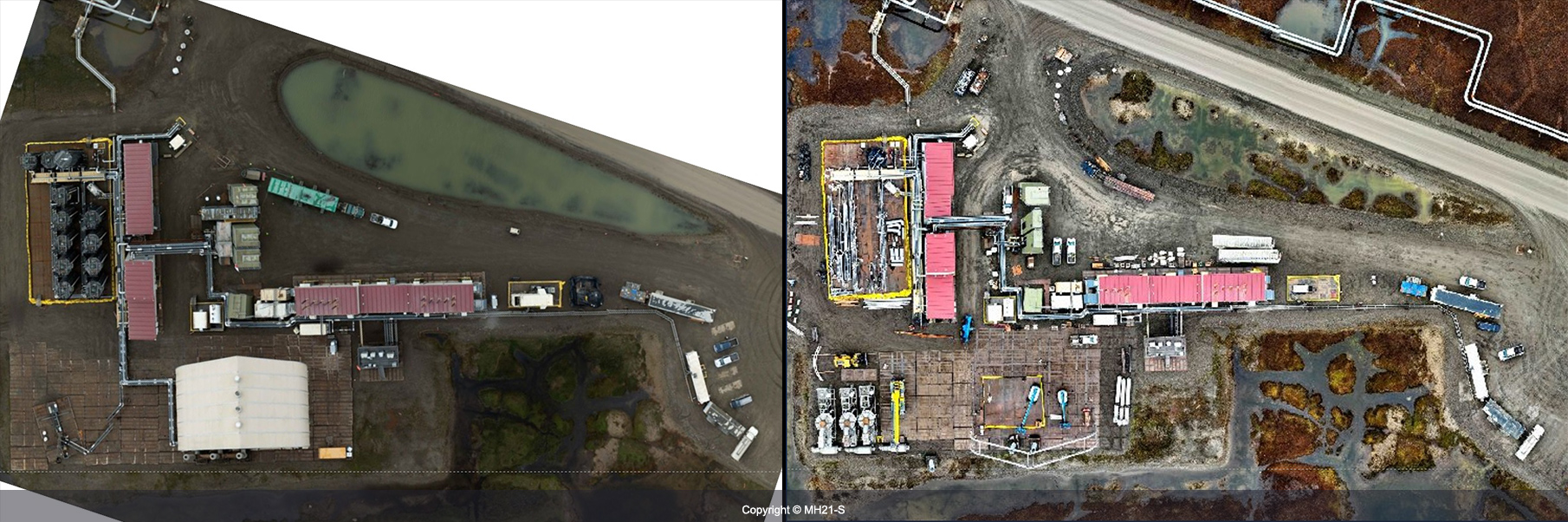 72)(Left) Overview of surface testing facilities as of July 2, 2024
(Right) Overview of surface testing facilities as of September 17, 2024 (Produced water tanks removed, Sprung structure removed) -
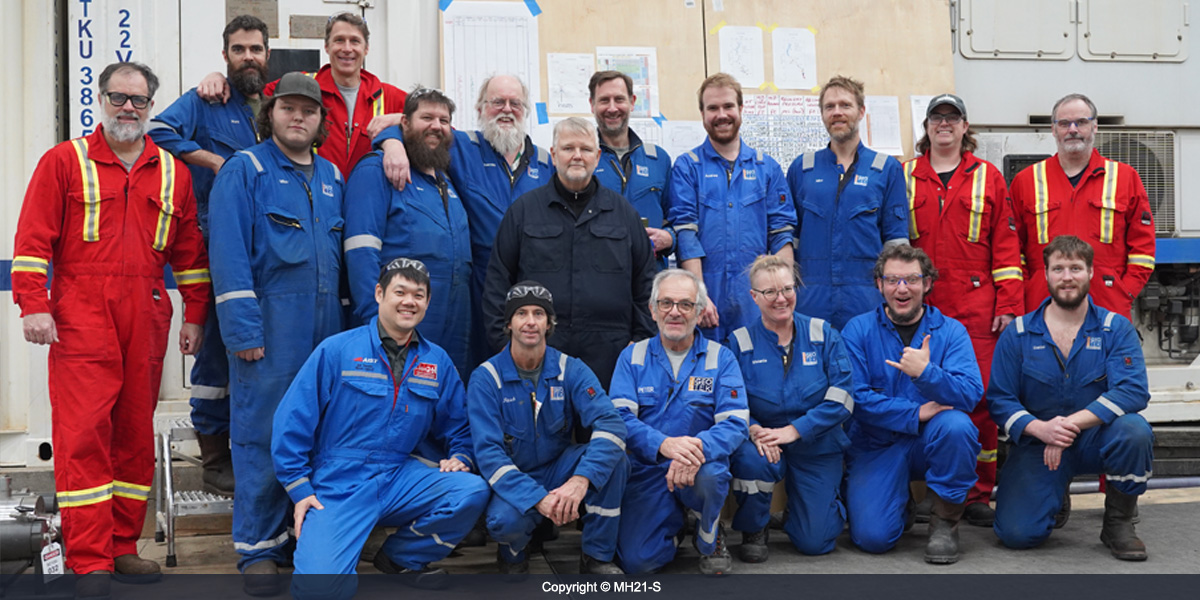
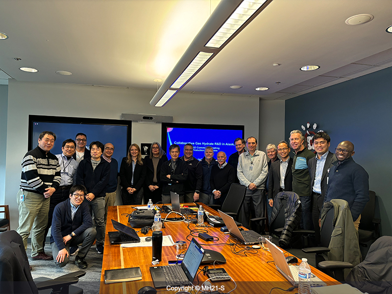
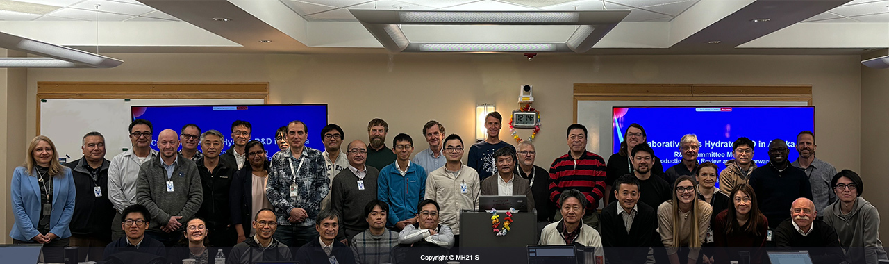 73)Participants of the Research & Development Committee Meeting (Nov 2024)
-
 74)Vibroseis(1)
-
 75)Vibroseis(2)
-
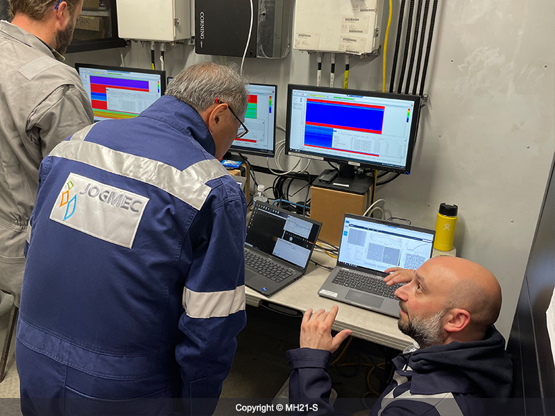
 76)Checking acquired seismic data
-
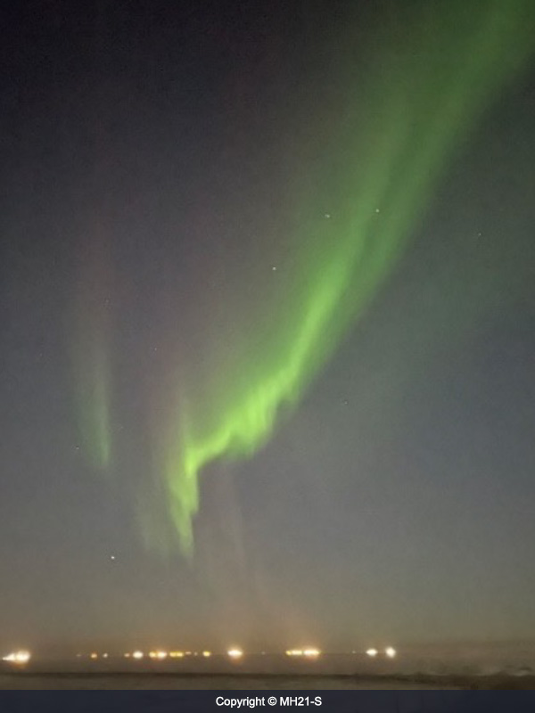
 77)Aurora(Mar 2025)
-
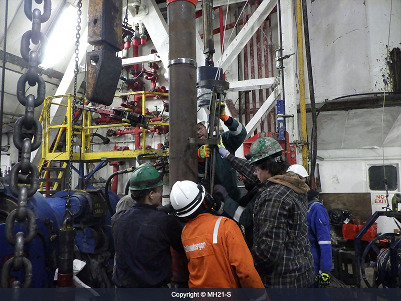
 78)Cable cutting
-
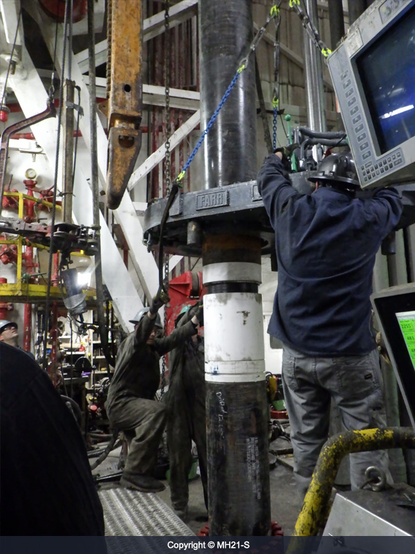
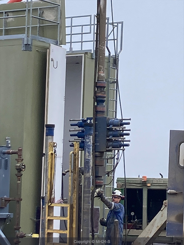
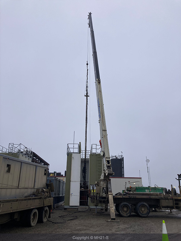
 79)Successfully completed pulling out of Sand control equipment
